The VMware HCX service – Exploring Integrated Services Configuration-3
- Now, select the cluster where the HCX services should be deployed, and click on CONTINUE, as shown in the following screenshot:
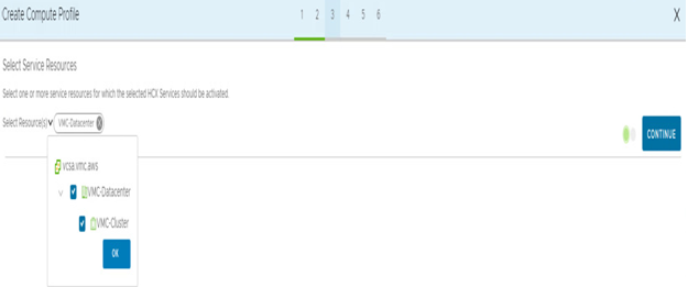
Figure 7.32 – HCX compute profile resource activation
- Now, we select the specific compute and storage allocation that the appliances will use and where they will be deployed. The folder placement selection is optional, as are the interconnect appliance resource reservations. After selection, click on CONTINUE, as shown in the following screenshot:
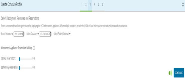
Figure 7.33 – Select Deployment Resources and Reservations
- Now, we will select the management network profile we previously created and click on CONTINUE, as shown in the following screenshot:

Figure 7.34 – Select Management Network Profile
- Now, select the uplink network profile, which is tied to the same management profile selected in the previous step, and click on CONTINUE, as shown in the following screenshot:
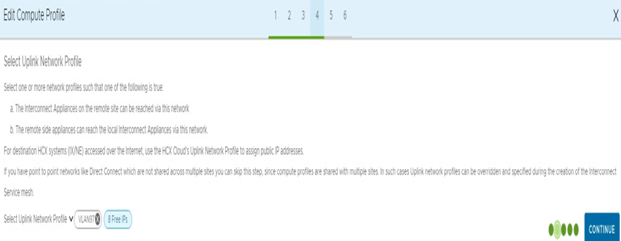
Figure 7.35 – Select a vSphere replication profile
NOTE
It’s possible to pair HCX appliances either using the internet or DX. If you would like to leverage DX for pairing, you must preconfigure the cloud-side HCX first using the following resource: https://vmc.techzone.vmware.com/resource/designlet-vmware-cloud-aws-sddc-connectivity-vmware-hcx-over-direct-connect.
- Next, select the vMotion network profile, which we created in the previous step, and click on CONTINUE, as shown in the following screenshot:

Figure 7.36 – Select vMotion Network Profile
- Select the vSphere replication network profile; most users can use the same profile as the management network profile unless a dedicated network is used. After selection, click on CONTINUE, as shown in the following screenshot:

Figure 7.37 – Select vSphere Replication Network Profile
- Choose the network vSphere Distributed Switch (vDS) used for the Layer 2 network extension service. After selection, click on CONTINUE, as shown in the following screenshot:

Figure 7.38 – Select Network Containers Eligible for Network Extension
- Now, review the network connectivity that will be required. This is useful when needing to coordinate with security teams. Click on CONTINUE, as shown on the following screenshot:

Figure 7.39 – Review Connection Rules
- Now, the user can review the final configuration of the compute profile and click on FINISH, as shown in the following screenshot:

Figure 7.40 – Ready to Complete
- Now, after we have completed the creation of the compute profile, we will establish a service mesh. To do so, navigate to the Service Mesh tab and click on CREATE SERVICE MESH, as shown in the following screenshot:

Figure 7.41 – HCX service mesh creation
- Select the Source and Destination sites and click CONTINUE, as shown in Figure 7.42:

Figure 7.42 – Select Sites
- Now, select the Compute Profile created previously on the on-premises HCX Manager. The Compute Profile on the HCX Cloud Connector on the VMware Cloud on AWS will be preconfigured during the HCX provisioning process. Click on CONTINUE, as shown in the following screenshot:
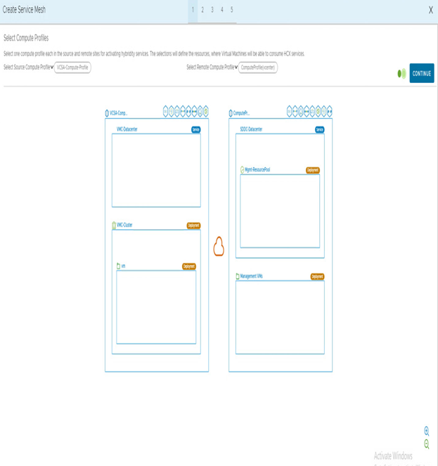
Figure 7.43 – Select Compute Profiles
- Now, users will need to confirm the services that will be activated with the service mesh. The services are deducted from the configuration previously made on the compute profile. Choose the services you would like to deploy and click on CONTINUE, as shown in the following screenshot:
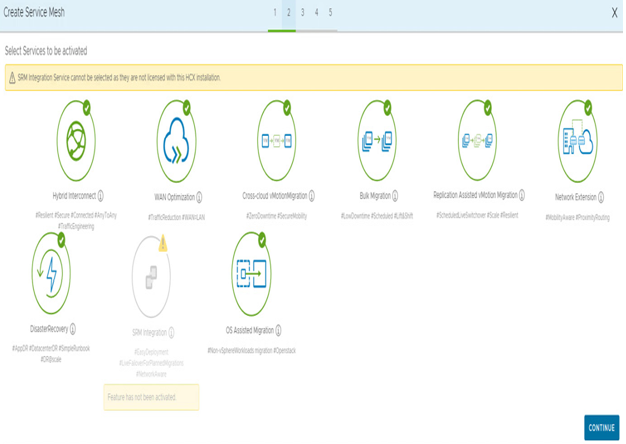
Figure 7.44 – Service mesh service selection
- Now, select the network uplink profiles. They will be used by the HCX-Interconnect (HCX-IX) service and HCX-Network Extension (HCX-NE) appliances defined in the previous steps with the management network profile. On the cloud side, select externalNetwork. Click on CONTINUE, as shown in the following screenshot:
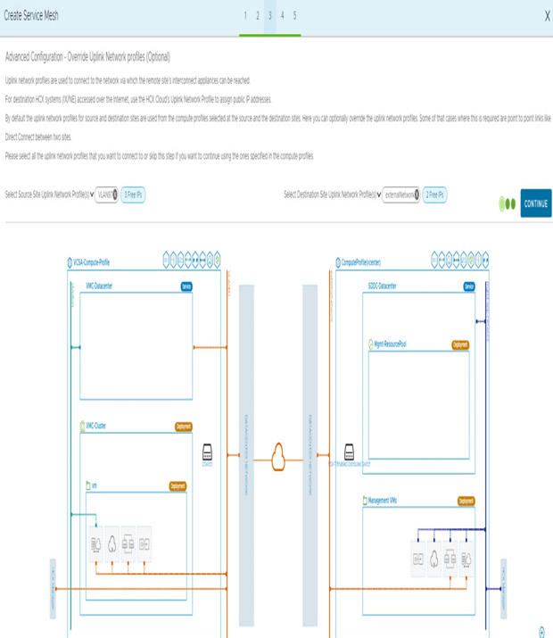
Figure 7.45 – Select an uplink network profile for the HCX service mesh
- We need to select the vSphere Distributed Switch (VDS) or NSX Virtual Distributed Switch (N-VDS) on the local side and map it to the remote network container on the cloud side. In addition, we will need to select the number of appliances deployed on the local side. Each network extension appliance can handle up to seven VLANs. If more VLANs require an extension, it is possible to deploy multiple appliances. Select the number of appliances, and then click on CONTINUE, as shown in the following screenshot:
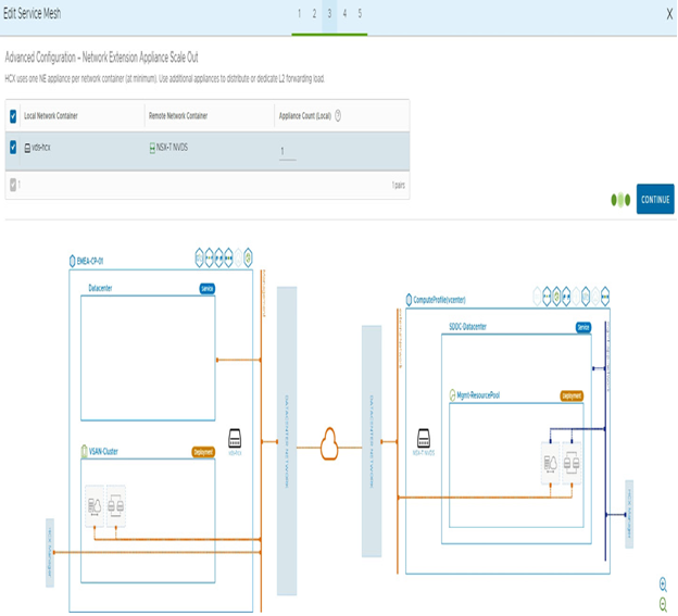
Figure 7.46 – Select the number of network appliances
- Now, users can select the advanced configurations. Those settings are optional and can be left unchecked. Application Path Resiliency is used to create multiple tunnels over the WAN to optimize multiple WAN paths, and TCP Flow Conditioning reduces packet fragmentation over WAN. Select the appropriate options, based on your WAN requirements, and click on CONTINUE, as shown in the following screenshot:
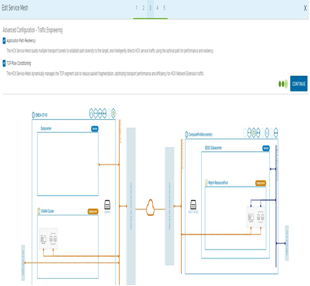
Figure 7.47 – Advanced configuration for the HCX service mesh
- Next, we review the topology, confirm there are no errors during the selection process, and then click on CONTINUE, as shown in the following screenshot:
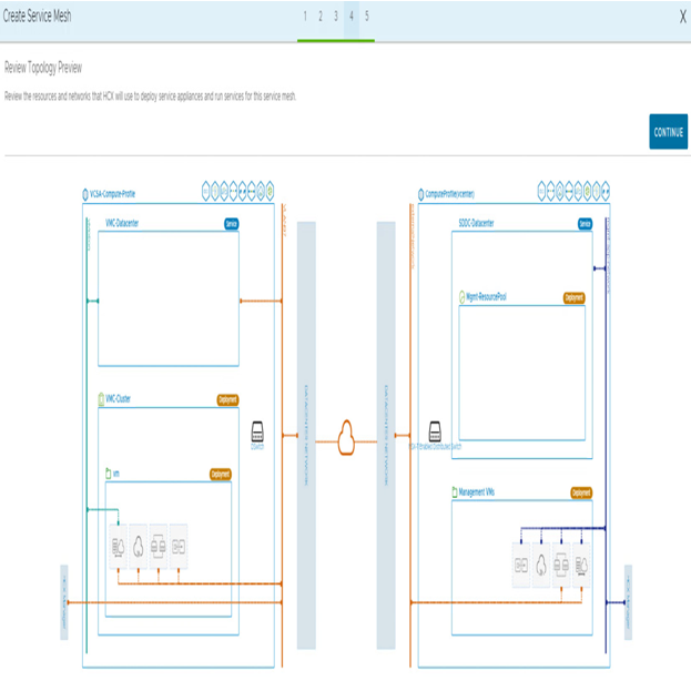
Figure 7.48 – Review Topology Preview
- Finally, we provide a name for the service mesh and click on FINISH, as shown in the following screenshot:
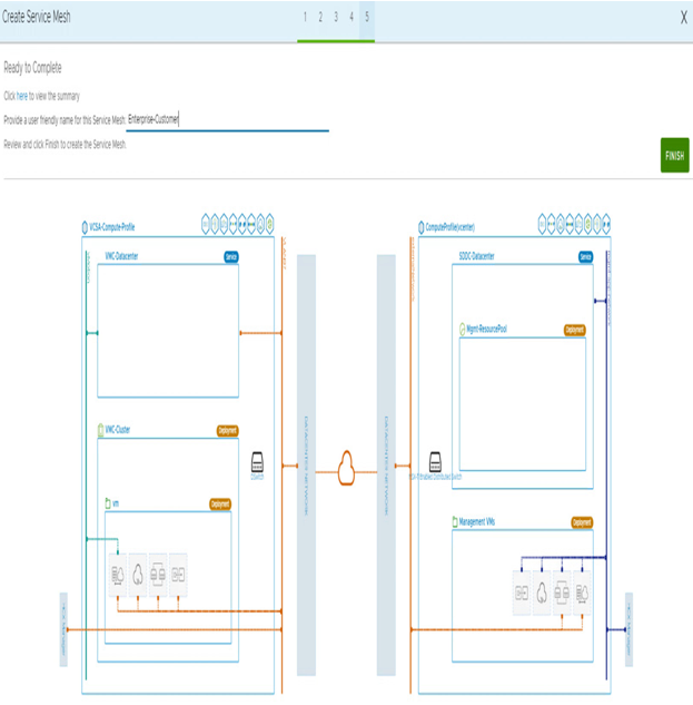
Figure 7.49 – HCX service mesh deployment confirmations
- After completing the configuration, the service mesh will deploy the appliances. Users can follow the progress through the Tasks tab, as shown in the following screenshot:
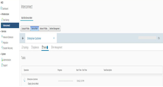
Figure 7.50 – HCX service mesh deployment
- Once the service mesh deployment process is completed, a green indication will appear in the Tasks tab, as shown in the following screenshot:
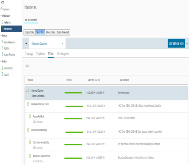
Figure 7.51 – HCX service mesh deployment confirmation
The service mesh has now been successfully deployed. Let’s configure the network extension in the next section.

