

Internet NAT – Understanding Networking and Security Configurations
Source NAT (SNAT) is automatically configured for all SDDC and tier-1 gateway workloads. SNAT is configured for translating the source IP of the VM into the internet public IP address assigned by the VMware Cloud on AWS SDDC. Therefore, customers do not need to create NAT rules for outbound traffic. The console does not present the default source NAT policy. The default translated IP address is visible in the Overview section, on the Home tab. It is labeled as Source NAT Public IP, as seen in the following screenshot:
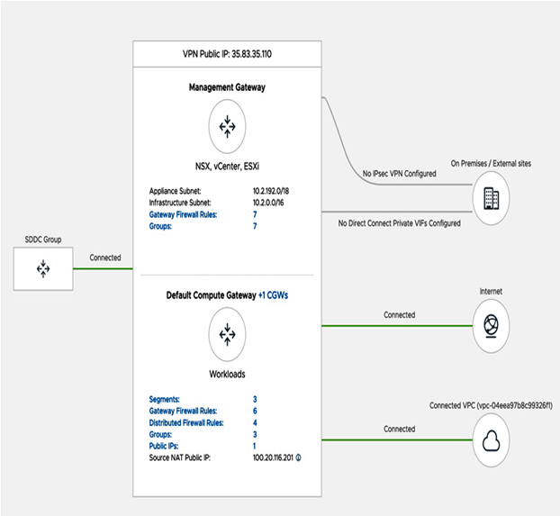
Figure 6.19 – Summary overview SNAT public IP address
The workload’s firewall blocks all communication to the internet to provide a secure environment by default. These workloads must be allowed to access the internet through this firewall.
A 1:1 NAT or DNAT is also possible for workloads running in VMware Cloud on AWS that must be exposed to the internet (for example, web servers). It’s necessary to request a public IP address from the VMware Cloud on AWS Management console. You will use the Public IPs section on the Networking tab, as seen in the following screenshot:

Figure 6.20 – Public IP request
Information
Public IPs are metered and charged, and customers are charged the standard AWS fee for a public IP. The VMware Cloud On AWS bill shows the public IP address fees.
Once the public IP has been assigned, it can be connected via NAT to a private IP for the VM. The configuration is in the NAT section on the Networking & Security tab. According to the policy in the example, all traffic towards port 80 from the internet will be translated into 10.22.23.45, as seen in the following screenshot:
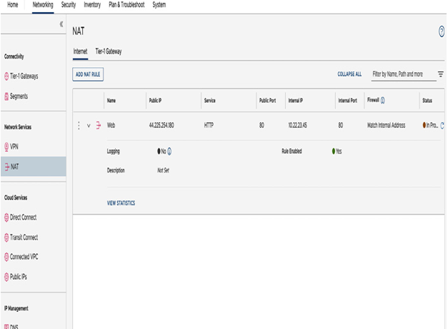
Figure 6.21 – Internet DNAT rule to the web server
Customers need to configure a firewall rule that allows internet access to the private IP addresses of the VM. As NAT is performed before inbound firewalling, the default firewall rule should refer to the private address.
For multiple tier-1 gateway configuration, the VM’s workloads could communicate with one another inside the SDDC and from the outside world.
However, we’ll need to configure route aggregation to enable a segment behind a tier-1 gateway to communicate to external resources over DX, vTGW, or to the SDDC’s Management segment.
Route aggregation is not required for internet access via an Internet Gateway (IGW).
Route aggregation
To configure route aggregation, select the Networking tab and navigate to Global Configuration, as seen in the following screenshot:
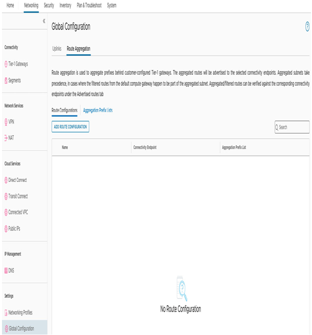
Figure 6.22 – NSX Manager standalone UI networking global configuration
In the upper – left corner, select Route Aggregation, and under Route Configurations, select ADD ROUTE CONFIGURATION, enter a description under Name, and select INTRANET under Connectivity Endpoint.
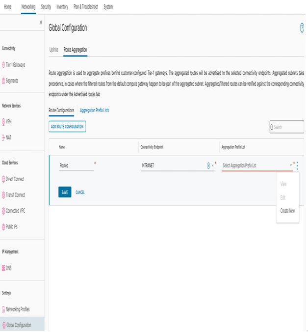
Figure 6.23 – Create a new route aggregation prefix list
Afterward, a pop-up message will appear for the Set Prefixes configuration. Click on ADD PREFIX and configure the unique non-overlapping CIDR 192.168.2.0/24 that we used for the NATted segment. In the event of multiple contiguous CIDRs, it is possible to summarize all the routes using a larger supernet route. Click on ADD and APPLY, as seen in the following screenshot:
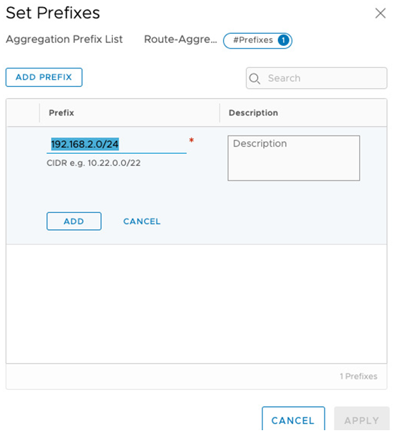
Figure 6.24 – Creating a prefix list for route aggregation
Afterward, provide a name and click on SAVE, as seen in the following screenshot:
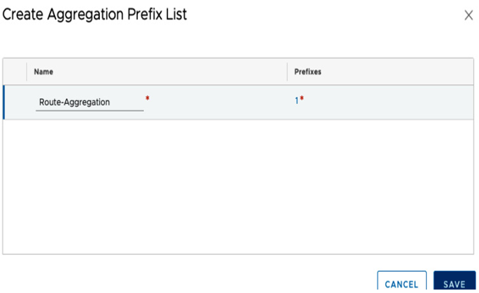
Figure 6.25 – Saving the aggregation prefix list configuration
After saving the configuration, we can confirm routes are being advertised to external entities by looking at the routing table under Advertised Routes. The Advertised Routes tab is visible under Transit Connect if it is in use. The configured prefix list of 192.168.2.0/24 advertised routes will appear with the Aggregated tag, as seen in the following screenshot:
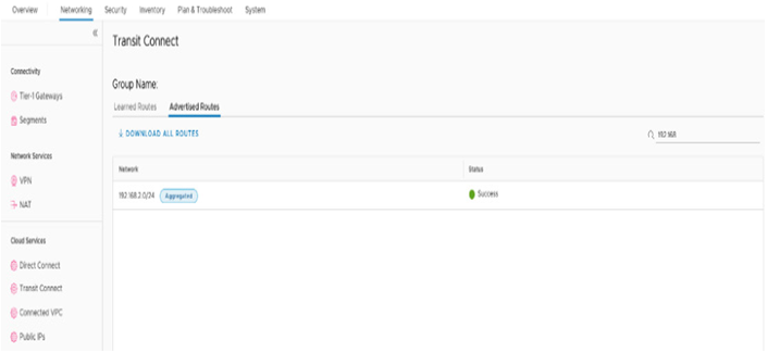
Figure 6.26 – Aggregated advertised routes under Transit Connect
Information
The Transit Connect routes will appear if an SDDC group has been configured. There will be more on SDDC groups later in this chapter.