

INFORMATION – Understanding Networking and Security Configurations
For further details on CMA topology and design, please refer to the Tech Zone design at https://vmc.techzone.vmware.com/resource/designlet-vmware-cloud-aws-static-routing-multiple-cgws-t1s#section3.
To create a new tier-1 gateway, let’s navigate to Tier-1 Gateways under Networking and click on ADD TIER-1 GATEWAY, as seen in the following screenshot:
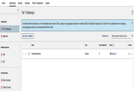
Figure 6.11 – Tier-1 Gateways view
Next, enter the name for Tier-1 Gateway Name. The name will appear later when we associate segments with the gateway and set the gateway type as Routed, as seen in the following screenshot:
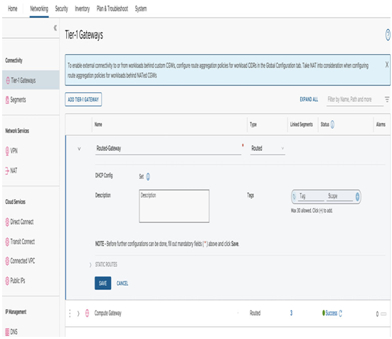
Figure 6.12 – Create a new Tier-1 Gateway
The other option types for gateways are NATted and Isolated. The type is selected during the provisioning process but can be edited after the creation.
By default, there are no segments associated with the newly provisioned gateways. This can be viewed in the #Linked Segments column, as seen in the following screenshot:
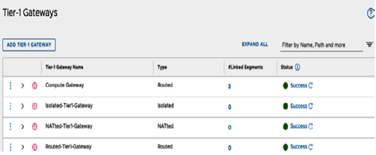
Figure 6.13 – Multiple Tier-1 Gateways provisioned
To associate segments to created tier-1 gateways, we’ll navigate back to the Segments section under Networking. Once we create a new segment in the Connected Gateway section, we’ll be able to select the newly created Tier-1 gateways and create an overlapping CIDR segment associated with a new NATted tier-1 gateway. In this example, 10.22.12.2/23 is tied to Routed-Gateway, when there is another segment with the same CIDR connected to Compute Gateway, as seen in the screenshot:
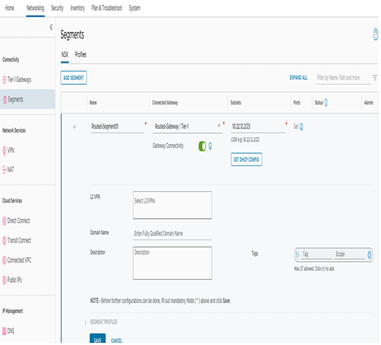
Figure 6.14 – Associating a segment to a new tier-1 gateway
To overcome the overlapping CIDR segment communication IP collision problem, we’ll create a Destination Network Address Translation (DNAT) rule for communications targeted toward the overlapping CIDR segment and a Source NAT (SNAT) rule for communications originating from the overlapping CIDR segment within the SDDC.
To create the NAT rules for the NATted gateway, navigate to the NAT section under Networking and select the NATted tier-1 gateway, as seen in the following screenshot:
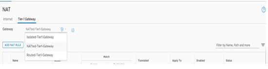
Figure 6.15 – Create a NAT rule for overlapping segments
Afterward, click on ADD NAT RULE, provide it with a name, and under Action, select DNAT. The Match Source field can remain empty, the Destination field will be a unique non-overlapping CIDR 192.168.2.0/24, and the Translated field will be the duplicated segment address of 10.22.12.0/24. Then click on SAVE, as seen in the following screenshot:
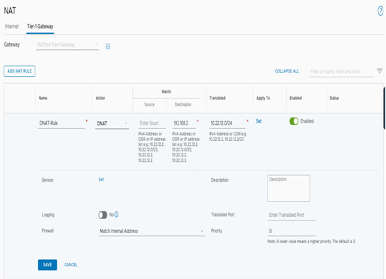
Figure 6.16 – Create a DNAT rule for overlapping segments
To create a SNAT rule, click on ADD NAT RULE under Action, select SNAT in the Match Source field, and add the duplicated CIDR segment 10.22.12.0/24. The Destination field can remain empty, and the Translated field will be the unique non-overlapping CIDR 192.168.2.0/24. The configuration is a mirror of the DNAT rules. Click on SAVE to complete the configuration, as seen in the following screenshot:
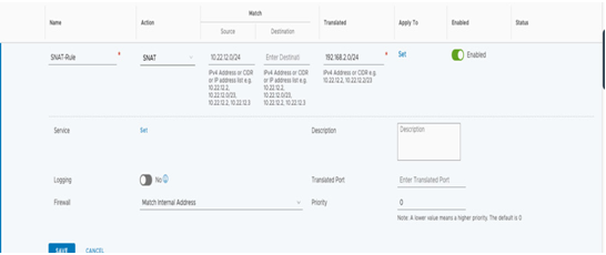
Figure 6.17 – Create a SNAT rule for overlapping segments
After the creation of the rules, the following configuration should appear under NATted-Tier-1 -Gateway, which will allow communication to and from the duplicate CIDR subnet, as seen in the following screenshot:
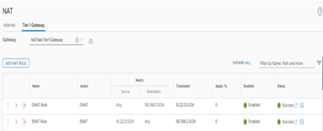
Figure 6.18 – NAT configuration summary